E155 Lab 4: Digital Audio
Introduction
In this lab the STM32L432KC Microcontroller Unit (MCU) was used to play music on a speaker. The MCU did this by generating a square wave at a specific frequency for a specific duration. The system was able to play Für Elise by Beethoven and Faded by Alan Walker as part of testing the functionality.
Experiment Setup and Design Overview
The main purpose of the lab was to learn how to read the manual and figure out how to set up different peripherals and the I/O of the MCU to perform the desired function. This includes initializing the proper structures and logic which are essential to run functions and extract performance out of the MCU. The MCU was set up to read a program containing a list of notes (shown as their frequency in Hz) and duration (shown in ms) to play the desired music.
MCU Setup Logic
To set up the MCU for the desired function, we had to configure different modules to run the system clock, set up timers, pre-flash functions, and configure the GPIO to use. To do this, we had to set up respective Header files to interface these functionalities. The header files setup were: RCC.h,the Reset & Clock Control (RCC) module to set up the system clock; GPIO.h, used to configure GPIO functions and enable parameters for other peripherals and TIM6_7.h, used to setup and configure parameters for the basic timers.
The MCU features timers that have specific channels for PWM generation (TIM2, TIM3, TIM15, & TIM16). They can be configured for PWM using output compare mode (CCR) and different prescaler values and auto-reload settings (ARR) to set up PWM frequencies and duty cycle. This approach was a challenge for me in terms of configuring the relevant registers and structures to perform PWM on TIM15 or TIM16 properly. The major issue is that if one bit is configured wrong, it renders a register useless, and this will yield no output on the circuit; it was hard for me to debug even with an oscilloscope. I elected to use the basic timers TIM6 and TIM7 to perform the tasks for this lab, which was simpler as I had full control over the behaviour of the counters. The main idea was to configure each timer’s prescaler and ARR so that the counters overflow at predictable intervals and then constantly check the timer’s status register (SR) for when the UIF bit is set. For delays, TIM6 runs until it overflows at the desired duration, at which point the UIF is cleared to acknowledge completion. For PWM generation, TIM7 is configured to overflow at half of the desired wave period, which is used to time each high- and low-phase of the square wave.
Implementation
Each timer is driven by the system clock (4MHz) and is divided using the AHB prescaler down to 1MHz to set the peripheral clock (HCLK) for all timers, following the equation below:
\[ \text{HCLK} = \frac{\text{SYSCLK}}{\text{AHB Factor}} = \frac{\text{4MHz}}{4} = \text{1MHz} \tag{1}\]
The HCLK was further divided down to set the counter frequency of TIM6 to 1kHz, meaning that each tick was exactly 1ms. This scaling allowed me to implement the delay functionality by setting ARR = dur – 1, where dur is the desired frequency duration, and waiting until the UIF flag is raised. TIM6 count frequency was obtained by setting TIM6 prescaler (PSC) to PSC = 999 as shown below:
\[ f_\text{TIM6} = \frac{\text{HCLK}}{(\text{PSC}+1)} = \frac{\text{1MHz}}{(999+1)} = \text{1kHz} \tag{2}\]
For PWM generation, both TIM6 and TIM7 are used together. TIM6 measures the total pulse duration by overflowing after dur milliseconds. Since we configured TIM7 to drive a PWM output in toggle mode, the hardware toggles the output every overflow. This means that the output signal is two overflows long (one rising and one falling edge). Therefore, to generate the desired frequency, TIM7 is configured to overflow every half-period of the desired frequency (run at twice the desired frequency), given a 1MHz timer frequency as shown below:
\[ T_\text{half} = \frac{1}{2f_\text{PWM}} = \frac{1,000,000}{2 f_\text{PWM}} \text{µs} \tag{3}\]
This is used to time each high- and low-phase of the square wave. Inside the PWM loop, the GPIO pin is driven high for one half-period, then low for the next half-period, with each phase timed by constantly checking UIF on TIM7, the wave timer. The process continues until UIF on TIM6 indicates that the total duration has expired. Suppose the overall delay timer finishes in the middle of a PWM cycle. In that case, the code breaks out instead of doing another half-period, essentially handling one of the edge cases in PWM generation. Also, the UIF bit is cleared after each wait, ensuring the next period is measured accurately.
This logic avoids system interrupts because the UIF is polled directly, allowing all control to be done in software. This keeps the CPU busy through wait loops, limiting it to only one function, as this also makes debugging easier. This works for this lab, as the CPU doesn’t need to perform any other functions simultaneously or otherwise, I would have to use interrupts.
Verification of Timer Limits and Edge Cases
Delay Limits
The delay timer, TIM6, runs at a counter frequency of \(1kHz\), where one tick is equivalent to \(1ms\). The overflow period for the timer is obtained through:
\[ t_\text{delay} = \frac{(ARR + 1)}{f_\text{TIM6}} \tag{4}\]
- The minimum delay can only be achieved when
ARR = 0since it can never be negative. Therefore:
\[ t_\text{delay} = \frac{(0 + 1)}{\text{1kHz}} = 1ms \tag{5}\]
- TIM6 has a 16-bit counter, therefore maximum delay can only be achieved when
ARR = 65,535. Therefore:
\[ t_\text{delay} = \frac{(65535 + 1)}{\text{1kHz}} = 65.536s \tag{6}\]
With a counter frequency of \(1 kHz\), TIM6 supports a duration within the range of 1 ms to 65.536 s, with 1 ms resolution, which is more than enough for the desired application in this lab.
PWM Frequency Limits
The PWM wave timer, TIM7, runs at HCLK which is \(1MHz\) and is toggled on each overflow. As mentioned before in the Implementation section above, TIM7 has to toggle at twice the desired rate to ensure the output square wave comes out as desired. The frequency of the toggled square wave is determined by Equation 7 below:
\[ f_\text{PWM} = \frac{\text{HCLK}}{2(ARR + 1)} \tag{7}\]
- Equation 7 above shows that the PWM frequency is inversely proportional to
ARR. Therefore minimum toggle frequency exists at the maximum possibleARRvalue,ARR = 65,535. Therefore:
\[ f_\text{PWM} = \frac{1,000,000}{2(65535 + 1)} = 7.629Hz \tag{8}\]
- Following similar logic, maximum toggle frequency exists at the minimum possible
ARRvalue,ARR = 0. Therefore:
\[ f_\text{PWM} = \frac{1,000,000}{2(0 + 1)} = 500kHz \tag{9}\]
With a timer frequency of \(1MHz\), TIM7 supported frequencies range calculated above encompasses the desired frequency range of 220Hz to 1000Hz sufficient for our applications.
Song Playing Accuracy
The durations were pretty much accurate because TIM6 was confugured with a period in milliseconds. The desired duration was directly equivalent to the ARR used in Equation 4. The ARR input into the equation was calculated using the equation below:
\[ \text{ARR} = \text{duration} - 1 \tag{10}\]
This meant that going into calculations the period divider was equivalent to the actual millisecond delay desired.
For the frequencies, the ARR input into TIM7 was calculated using the half-frequency division to allow running both rising and falling edges of the square wave within the timing window set by the delay. It was obtained using the following equation:
\[ \text{ARR} = \frac{\text{HCLK}}{2f_\text{PWM}} - 1 \tag{11}\]
- If the desired frequency was 220Hz then, Equation 11 gives \(ARR\approx 2272\). Substituting this in Equation 7 gives toggle frequency, \(f_\text{toggle} = 219.97Hz\), equivalent to a 0.014% error.
- If the desired frequency was 1000Hz then, Equation 11 gives \(ARR\approx 499\). Substituting this in Equation 7 gives toggle frequency, \(f_\text{toggle} = 1000Hz\), equivalent to a 0.00% error.
This proves that individual pitches are accurate within 1% across the frequency range of 220-1000 Hz as desired, therefore verifying precision and accuracy of the design.
Hardware Testing and Results
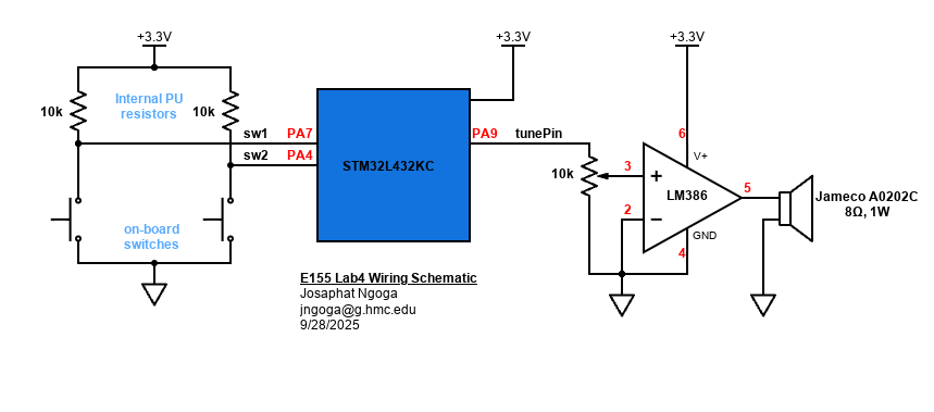
After verifying the MCU logic, the code was uploaded on the hardware for testing using Segger Embedded Studio. The setup used onboard switches connected to pins A7 and A4 of the MCU. These pins were used to switch between the two available songs. The switches were configured by activating the onboard \(10k\Omega\) pull-up resistors through the dedicated PURPDR GPIO function. The MCU toggle output through pin A7 was fed into a \(10k\Omega\) potentiometer for volume control, which sent it to the non-inverting input of the LM386 op-amp. The ouput of the op-amp (analog signal) went to the speaker to play the chosen song. All components were collected and assembled on an extended breadboard following the schematic below:
The hardware responded properly as shown in the example video below:
Conclusion
This lab took around 19 hours to complete. A lot of time was spent figuring out how to set up the proper registers for timers as well as other functions I epected to use with my MCU. It was also hard to debug since unlike the FPGA, when anything is wrong, you don’t get any output which is different from the FPGA where you get a wrong output and could debug from there. The errors I found were through register instantiation and some typos like negative signs in the implementation that were not caught by the compiler. Resolving all of this allowed me to get my hardware playing music properly.
AI Prototype Summary
The goal of this prototype is using AI as a documentation search assistant to navigate memory maps and guide the configuration of various peripherals. I used Chatgpt 5 to run the different prompts and it gave me the following results:
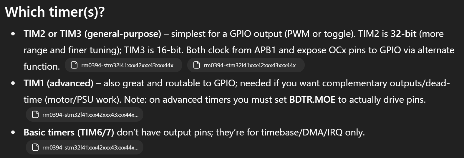
- The AI was able to recognisze the different types of registers that could be used, identified the pros and cons of using either, and also managed to predict the full course all the way from instantiating registers to implementing CCR, prescaler, and ARR functionality. However this was after I passed the STM32L4 reference manual along with the prompt. Figure 3 below shows this initial realization:
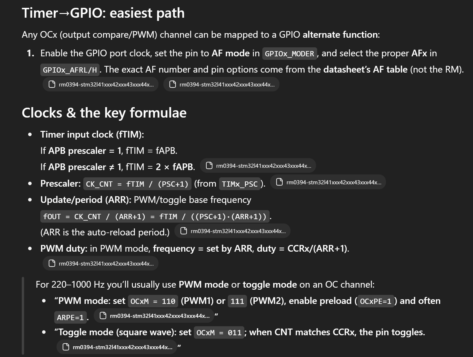
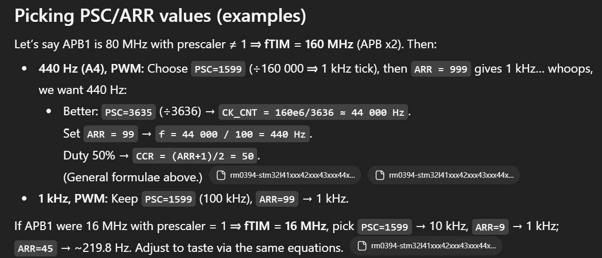
- After Identifying potential timers to use for the desired PWM generation, the LLM also correctly identified how to calculate the ARR, frequency, duty cycle, and necessary prescalers to perform the functions. Figure 4 below shows this implementation:
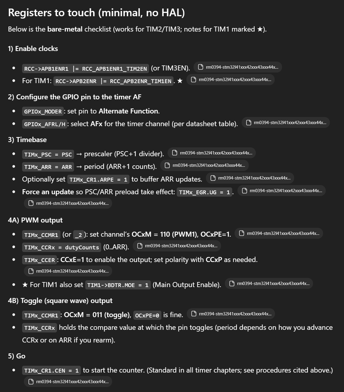
- After correctly identifying the timers, the LLM went on to initalize all the necessary registers in proper steps. Figure 5 below shows this implementation:
- Here is also an example provided to show the use of the different register declarations. This shows me that the LLM got the idea on what to do and how to setup to achieve the desired frequency RPM and durations as shown in Figure 6 below:
- Lastly, the LLM provided an example code to show how it could drive the pins to generate a frequency. The code enables timers, configures GPIO, ARR and Prescalers, the code also implements a ms delay function to ensure separation between different frequencies driven.
// Simple PWM tone generator on STM32L432KC
// Output: PA0 = TIM2_CH1 (AF1)
// Freq range: 220 Hz – 1 kHz (works for others too)
// Toolchain: bare-metal with CMSIS headers

#include "stm32l4xx.h"

#define TIM2CLK_HZ   80000000UL   // Adjust if your clock tree differs
#define TARGET_TICK  1000000UL    // We prescale timer to 1 MHz for easy math (1 tick = 1 us)

static inline void tim2_set_freq(uint32_t freq_hz) {
    if (freq_hz == 0) {
        // Stop output
        TIM2->CCER &= ~TIM_CCER_CC1E;
        return;
    }

    // With timer tick at 1 MHz, ARR = (1e6 / f) - 1
    uint32_t arr = (TARGET_TICK / freq_hz) - 1U;
    if (arr < 1) arr = 1;  // guard

    // Use 50% duty: CCR1 = (ARR+1)/2
    uint32_t ccr = (arr + 1U) / 2U;

    // Update safely using preload + UG
    TIM2->ARR  = arr;
    TIM2->CCR1 = ccr;
    TIM2->EGR  = TIM_EGR_UG;     // latch PSC/ARR/CCR
}

// crude delay
static void delay_ms(uint32_t ms) {
    // ~4 cycles per loop at -O2 on Cortex-M4F; tweak if needed
    // For simplicity, use a coarse busy wait:
    volatile uint32_t n = ms * 16000UL; // assuming 64–80 MHz core; it's okay if approximate
    while (n--) __NOP();
}

int main(void) {
    // --- 1) Enable clocks ---
    RCC->AHB2ENR  |= RCC_AHB2ENR_GPIOAEN;       // GPIOA clock
    RCC->APB1ENR1 |= RCC_APB1ENR1_TIM2EN;       // TIM2 clock

    // --- 2) Configure PA0 as AF1 (TIM2_CH1) ---
    // PA0: MODER=10 (AF), AFRL0=0001 (AF1), push-pull, high speed
    GPIOA->MODER   = (GPIOA->MODER & ~(3U << (0*2))) | (2U << (0*2)); // AF
    GPIOA->AFR[0]  = (GPIOA->AFR[0] & ~(0xFU << (0*4))) | (1U << (0*4)); // AF1
    GPIOA->OSPEEDR |= (3U << (0*2));   // high speed (optional)
    GPIOA->OTYPER  &= ~(1U << 0);      // push-pull
    GPIOA->PUPDR   &= ~(3U << (0*2));  // no pull (or set to taste)

    // --- 3) Configure TIM2 base to 1 MHz tick ---
    // PSC = TIM2CLK/TARGET_TICK - 1 -> 80 MHz / 1 MHz - 1 = 79
    TIM2->CR1   = 0;                   // upcount, edge-aligned
    TIM2->PSC   = (TIM2CLK_HZ / TARGET_TICK) - 1U;
    TIM2->ARR   = 999;                 // placeholder (1 kHz initially)
    TIM2->CCR1  = 500;                 // 50% duty

    // PWM mode 1 on CH1 + preload
    // OC1M = 110 (bits 6:4), OC1PE=1 (bit 3)
    TIM2->CCMR1 &= ~((7U << 4) | (1U << 3));
    TIM2->CCMR1 |=  (6U << 4) | (1U << 3);

    // Enable output on CH1 (active-high)
    TIM2->CCER  &= ~((1U<<1) | (1U<<3)); // CC1P=0, CC1NP=0
    TIM2->CCER  |=  (1U<<0);             // CC1E=1

    // Enable ARR preload and latch settings
    TIM2->CR1   |= TIM_CR1_ARPE;
    TIM2->EGR    = TIM_EGR_UG;

    // --- 4) Start timer ---
    TIM2->CR1   |= TIM_CR1_CEN;

    // --- Demo: cycle a few musical-ish tones ---
    while (1) {
        tim2_set_freq(220);  // A3
        delay_ms(800);
        tim2_set_freq(440);  // A4
        delay_ms(800);
        tim2_set_freq(880);  // A5
        delay_ms(800);
        tim2_set_freq(1000); // 1 kHz
        delay_ms(800);
    }
}
The code provided seems resonable to me. It configures TIM2 for PWM generation, same way I could have done with TIM15. It calls the necessary structures such as CR1, CCR, PSC, and ARR. The code compiles of course except for some specific variables the LLM probably defined in the assumed stm32l4xx.h header file. I didn’t test the code on hardware, but from what I analyzed so far I believe it works well. The LLM also uses the crude delay with the assembly __nop function.