E155 Lab 5: Interrupts
Introduction
In this lab, the MCU was used to interface with a quadrature encoder to measure the speed (in revolutions/sec) and direction (Clockwise/anti-clockwise) of a DC motor. The MCU did this by using the encoder mode of the advanced timer, TIM1, and using the basic timer, TIM6, to sample the incoming wave, calculating position difference and direction. In the end, the design could display the motor speed as well as the direction, accounting for instances when the motor is also at rest.
The quadrature encoder in this lab uses a motor to trigger Hall effect sensors, which output two square waves that are \(90^\circ\) out of phase. This phase difference is what was used to determine the period of the waves and hence calculate the speed and direction of the motor.
Experiment Setup and Design Overview
The main purpose of the lab was to use interrupts to interface with the encoder by triggering interrupts on the edges of the encoder pulses following a sampling time of \(0.083 s\), to find the difference in positions, which was then used to determine both the direction and speed of the motor. The design measured and displayed the motor speed in rev/s with an update of at least \(1Hz\).
MCU Setup Logic
To set up the MCU for the desired function, we had to configure different modules to run the system clock, set up timers, and configure GPIO. This time, we were allowed to use the CMSIS library, which meant that all the register structs for the MCU were predefined, which simplified the code and design. The libraries also had some added functionality from the functions and logic set up in the previous lab, as some of it, such as configuring timers, was used in this lab as well. The given motor had \(PPR = 408\), so with a quadrature encoder, I set PULSES_PER_REV = 1632.
I leveraged encoder interface mode 3 for TIM1, which allows me to connect an incremental encoder directly to the timer. Pins PA8 and PA9 were configured for alternate function and connected to the two TIM1 channels. The signals from the encoder came in through these pins, and each complete quadrature cycle (both rising and falling edges of both channels) increments or decrements the counter. The counter direction is set in the hardware direction bit (obtained from TIM1->CR1 & TIM_CR1_DIR) and is also used to determine the effective direction and position of the motor. The counter limit, ARR, was set to ARR = PULSES_PER_REV - 1 so TIM1 counter wraps once per mechanical revolution. This wrap-around logic identifies the difference between the past recorded and current motor position (essentially 2 different values of TIM1 counter) and turns it into the smallest, correctly signed motion across a wrap. The sign of this difference is what is used to determine the direction. The difference is mapped into the nearest step around a circle by comparing it to PULSES_PER_REV /2. If less, I subtract PULSES_PER_REV and vice versa. However, if a sample occurs at the half turn, I use the direction provided by the TIM1 hardware direction bit. This logic ensures proper signage every time: for example, moving from \(400\) to \(10\) would give a difference of \(-390\). Which would be the wrong motor direction, but after applying the wrap logic, I get \(18\), which shows me the actual step completed and the right direction (sign).
A separate timer, TIM6, runs at the sample period of \(0.083s\) with a \(1KHz\) clock (obtained by prescaling down the \(4MHz\) system clock). TIM6 ISR snapshots TIM1->CNT and the value is recorded and used to determine motor position. The major concern with this sampling approach aliasing. My safe zone is valid as long as the shaft moves less than half a revolution per sample. This means the chosen sample period of 0.083s is valid as long as \(rps*0.083< 0.5\), which means my wrap-around logic works up to \(\approx6Rev/s\) (360rpm), which is more than enough since the given motor does \(2Rev/s\) at 10V and around \(5Rev/s\) at 24V.
Implementation
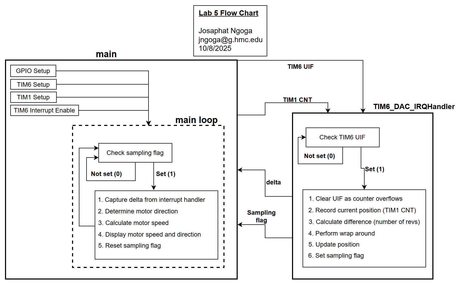
The main function communicates with TIM6 interrupt handler through only a few set of select signals that set up the whole functionality. TIM6 is configured as a basic timer with a prescaler and ARR to generate interrupts every 0.083s and sets UIF bit. On each interrupt, the handler reads the current value of TIM1->CNT and compares it to the previous value. The difference is adjusted for wrap-around using the logic described above and the ISR sets sample = 1 signaling the main loop to calculate and print values. The main loop waits for the interrupt to update the position and direction based on the difference calculated in the IQR function. The loop would print values and then reset the sample flag. This can be seen in Figure 1 below:
An alternative to periodic-interrupt sampling is polling, where the TIM6 update interrupt flag (UIF) is checked frequently in the main() loop, and samples are taken when the flag is set. While polling can be simpler to implement, it is generally less efficient because the CPU must continuously check the flag, consuming more processing resources and potentially missing other important tasks such as printing, calculation, or reading encoder signals. If we were to ensure the CPU does all of this while polling, the design would have a timing error that would invalidate the speed measurements.
Given the system parameters (clk, sample period, PPR) described above, the implementation follows the baseline math below assuming \(5 Rev/s\) top speed:
- Counts per sample: \(\text{RPS}*\text{T\_sample}*\text{PPR} = 5*0.083*1632 \approx 677 \text{counts}\), a value that is well below the alias limit of \(\frac{\text{PPR}}{2} = 816\text{counts}\)
- Counts per second: \(\text{PPR}*\text{RPS} = 1632*5 = 8160\text{counts/s}\)
Arm estimates the Core-M4 ISR latency(\(\epsilon\)) to be between \(10-25\mu s\). With TIM6 ISR triggering every 83ms, the relative timing error is \(\frac{\epsilon}{\text{T\_sample}} = \frac{25\mu s}{83ms} \approx 0.03\%\). Therefore the counting error would be \(677\text{counts}*0.03\% \approx 0.2\text{counts}\) which is very small compared to \(677\).
With a polling approach, the relative timing error depends on the polling interval, which is determined by how fast the main loop iterates. This interval can be easily affected by other tasks that the CPU must run simultaneously or in sequence. To match the same timing error as the interrupt method, the polling interval would need to be as short as \(25\mu s\). However, this interval only accounts for looping overhead—assuming 200 cycles at a 4MHz clock. When additional functions such as printing are included, CPU resources are stretched further and the interval can go as high as \(20-50ms\) assuming fasted baud rate. Given a polling inteval \(\tau=20ms\), the timing error is \(\frac{(\frac{\tau}{2})}{\text{T\_sample}} = \frac{(\frac{20ms}{2})}{\text{83ms}} \approx 12.05\%\). Therefore the counting error would be \(677\text{counts}*12.05\% \approx 82\text{counts}\) which is magnitude above the error from ISR.
This shows that using interrupts for encoder sampling is much more accurate and efficient than polling, as it minimizes timing errors and ensures reliable speed measurements.
Hardware Setup
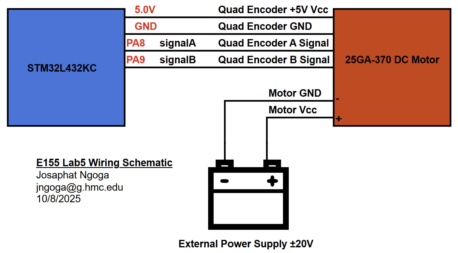
After verifying the MCU logic, the code was uploaded on the hardware for testing using Segger Embedded Studio. The quadrature encoder was connected to the +5V and GND from the MCU, and the signals were connected to the 5V-tolerant pins A8 and A9. The motor itself was connected to the lab power supply to with the ability to feed both negative and positive voltages to the motor in the range ±25V.
The hardware responded properly as shown in the example video below:
Conclusion
This lab took around 14 hours to complete. I invested a lot of time in making sure my sampling and wrap-around logic lines up properly for the intended approach in reading the speed of the motor. I had struggles mainly with sampling as I was aliasing a lot of times and the wrap around math was wrong because the PPR was divided in the timer setup initially but now it is all fixed and the setup works properly as shown in Figure 3.
AI Prototype Summary
The goal was to use AI to generate an interrupt based approach to interface a quadrature encoder. I used chatgpt5 and it generated the code snippet linked below.
// STM32L432KC - Quadrature via EXTI (PA0/PA1) + TIM7 speed print
// - A: PA0 -> EXTI0
// - B: PA1 -> EXTI1
// Prints speed (rev/s, RPM) and direction ("FWD"/"REV"/"STOP") at SAMPLE_HZ

#include "stm32l4xx.h"
#include <stdint.h>
#include <stdio.h>   // assume retargeted to UART/SWV

// ====== USER CONFIG ======
#define ENCODER_CPR      408u      // counts per revolution per channel (datasheet CPR)
#define SAMPLE_HZ        50u        // speed print rate (Hz) -> 20 ms period
#define TIMER_CLK_HZ     80000000u  // TIM7 input clock (APB1 timer clock). Adjust to your system.

// Derived: 4x decoding edges per rev
#define EDGES_PER_REV    ( (uint32_t)ENCODER_CPR * 4u )

// ====== Globals (shared with ISRs) ======
static volatile int32_t enc_pos = 0;     // accumulated 4x edges
static volatile int8_t  last_step = 0;   // last +1/-1/0 (for direction)
static volatile uint8_t prev_ab = 0;     // previous AB state (00,01,11,10 encoded as 0..3)

// 4-bit LUT: (prev<<2 | curr) -> {-1,0,+1}
static const int8_t quad_lut[16] = {
/* 00->00 */  0, /*00->01*/ +1, /*00->11*/ -1, /*00->10*/  0,
              -1,  0,        0,       +1,
              +1,  0,        0,       -1,
               0, -1,       +1,        0
};

// ====== Helpers ======
static inline uint8_t read_ab(void) {
    uint32_t idr = GPIOA->IDR;
    uint8_t a = (idr >> 0) & 1u;   // PA0
    uint8_t b = (idr >> 1) & 1u;   // PA1
    return (uint8_t)((a << 1) | b);
}

static inline void quad_step(void) {
    uint8_t curr = read_ab();
    int8_t delta = quad_lut[(prev_ab << 2) | curr];
    if (delta) {
        enc_pos += delta;
        last_step = delta; // remember sign for direction
    }
    prev_ab = curr;
}

// ====== GPIO + EXTI init for PA0/PA1 ======
static void enc_exti_init(void) {
    // Clocks
    RCC->AHB2ENR  |= RCC_AHB2ENR_GPIOAEN;
    RCC->APB2ENR  |= RCC_APB2ENR_SYSCFGEN;

    // PA0, PA1 as inputs with pull-up
    GPIOA->MODER  &= ~((3u<<(0*2)) | (3u<<(1*2)));
    GPIOA->PUPDR  &= ~((3u<<(0*2)) | (3u<<(1*2)));
    GPIOA->PUPDR  |=  ((1u<<(0*2)) | (1u<<(1*2)));  // PU

    // Route to EXTI0/1 from port A
    SYSCFG->EXTICR[0] &= ~((0xFu<<0) | (0xFu<<4)); // PA for EXTI0/1

    // Both edges on A and B
    EXTI->IMR1  |=  (1u<<0) | (1u<<1);
    EXTI->RTSR1 |=  (1u<<0) | (1u<<1);
    EXTI->FTSR1 |=  (1u<<0) | (1u<<1);

    // Initial AB state
    prev_ab = read_ab();

    // NVIC
    NVIC_SetPriority(EXTI0_IRQn, 2);
    NVIC_SetPriority(EXTI1_IRQn, 2);
    NVIC_EnableIRQ(EXTI0_IRQn);
    NVIC_EnableIRQ(EXTI1_IRQn);
}

// ====== TIM7 periodic (speed print) ======
static void tim7_init_sample_timer(void) {
    // Enable TIM7 clock
    RCC->APB1ENR1 |= RCC_APB1ENR1_TIM7EN;

    // Compute PSC/ARR for SAMPLE_HZ
    // We aim for: TIM7 tick = 1 MHz (1 us) to keep ARR small & precise
    uint32_t target_tick_hz = 1000000u; // 1 MHz
    uint32_t psc = (TIMER_CLK_HZ / target_tick_hz);
    if (psc == 0) psc = 1;
    psc -= 1;
    TIM7->PSC = (uint16_t)psc;

    // ARR = tick_hz / SAMPLE_HZ
    uint32_t tick_hz = TIMER_CLK_HZ / (psc + 1u);
    uint32_t arr = tick_hz / SAMPLE_HZ;
    if (arr == 0) arr = 1;
    arr -= 1;
    TIM7->ARR = (uint16_t)arr;

    TIM7->EGR  = TIM_EGR_UG;          // update registers
    TIM7->SR   = 0;                   // clear flags
    TIM7->DIER = TIM_DIER_UIE;        // update interrupt
    NVIC_SetPriority(TIM7_IRQn, 3);
    NVIC_EnableIRQ(TIM7_IRQn);
    TIM7->CR1  = TIM_CR1_CEN;         // start
}

// ====== Interrupts ======
void EXTI0_IRQHandler(void) {           // A changed
    if (EXTI->PR1 & (1u<<0)) {
        EXTI->PR1 = (1u<<0);           // clear
        quad_step();
    }
}
void EXTI1_IRQHandler(void) {           // B changed
    if (EXTI->PR1 & (1u<<1)) {
        EXTI->PR1 = (1u<<1);           // clear
        quad_step();
    }
}

void TIM7_IRQHandler(void) {
    static int32_t last_pos = 0;

    if (TIM7->SR & TIM_SR_UIF) {
        TIM7->SR &= ~TIM_SR_UIF;

        // Snapshot position atomically (enc_pos is 32-bit aligned, read is atomic on Cortex-M4)
        int32_t now = enc_pos;
        int32_t delta = now - last_pos;
        last_pos = now;

        // Convert delta edges to rev/s
        // revs_in_window = delta / EDGES_PER_REV
        // speed_rps = revs_in_window * SAMPLE_HZ
        float speed_rps = ((float)delta / (float)EDGES_PER_REV) * (float)SAMPLE_HZ;
        float rpm = speed_rps * 60.0f;

        // Direction: prefer sign of delta, otherwise use last edge sign, otherwise STOP
        const char *dir = "STOP";
        if (delta > 0)      dir = "FWD";
        else if (delta < 0) dir = "REV";
        else if (last_step > 0) dir = "FWD";
        else if (last_step < 0) dir = "REV";

        // Optional: deadband small jitter around zero
        const float eps_rps = 0.002f; // ~0.12 RPM
        if (speed_rps > -eps_rps && speed_rps < eps_rps) {
            speed_rps = 0.0f;
            rpm = 0.0f;
        }

        // Print once per sample
        printf("Speed: %.3f rev/s (%.1f RPM), Dir: %s, Pos: %ld edges\r\n",
               speed_rps, rpm, dir, (long)now);
    }
}

// ====== Example main ======
int main(void) {
    // (Init clocks here if not already done by your startup/system code)
    // (Init UART or SWO for printf elsewhere)

    enc_exti_init();
    tim7_init_sample_timer();

    while (1) {
        __WFI(); // sleep until interrupt (optional, saves power/CPU)
    }
}
After trying the code in my setup it didn’t work. The reasoning comes close to mine in terms of using a sampling timer but it used GPIO interrupts as opposed to timer encoder mode which I used. The LLM seems to be concerned about CPU resource usage which is good and has code to ensure the CPU uses less resources such as sleeping when an interrupt isn’t triggered. There is also code to ensure smooth filtering to remove encoder signal noise. Another great thing the LLM impemented is NVIM_SetPriority() which sets the order in which interrupts from the GPIOs and the timer are handled. It used this to ensure that encoder edges are processed before the speed readout updates.