Mechanical Design of The Actuation System
Overview
The actuation system was integral to the success of the project as it was the link responsibe for moving data from the sender side to the receiver side. It combines the necessary components which are: relay modules, solenoids, actuation shaft, as well as the limit swithces. To make sure these components work as desired, they had to be fixed in place. This was done by 3D printing different components/sections necessary to hold the 9 different channels together making it easier to carry around and neat. Information about the individual components can be found in Documentation.
N.B: All 3D printed parts are configured to be a tight fit of the relevant component they will be holding except for the part holding the acutation shafts. The clearance is + 0.1in from whatever dimension you want to constrain. For example the head of the solenoids has \(\text{Diameter } = 0.15in\) thus the 3D printed part will have \(\text{Diameter } = 0.16in\)
Component Design and Fitting
Relay Block and Modules
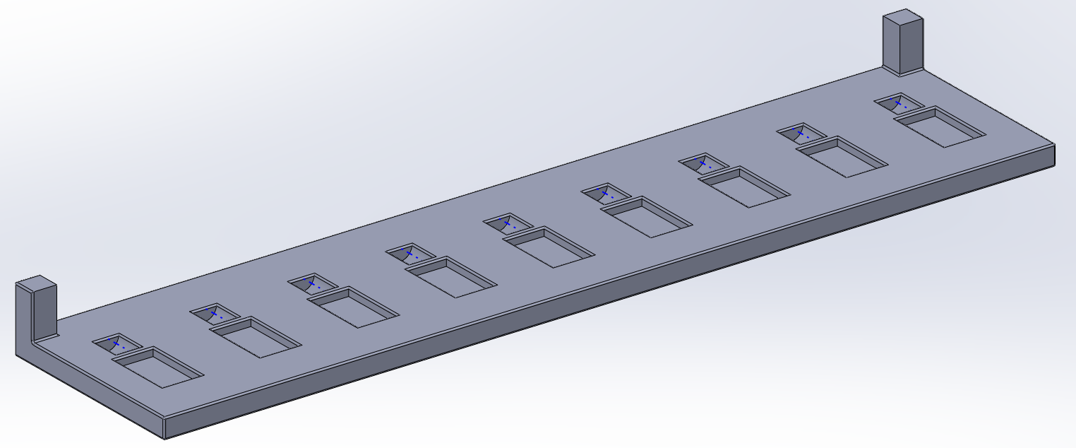
The relay block is one of the main components of the setup. It is meant to house the relay modules in place leaving square openings exposing the 6 screw terminals of the relay module for connectiing other components and terminals. The relay block is shown in Figure 1 below:
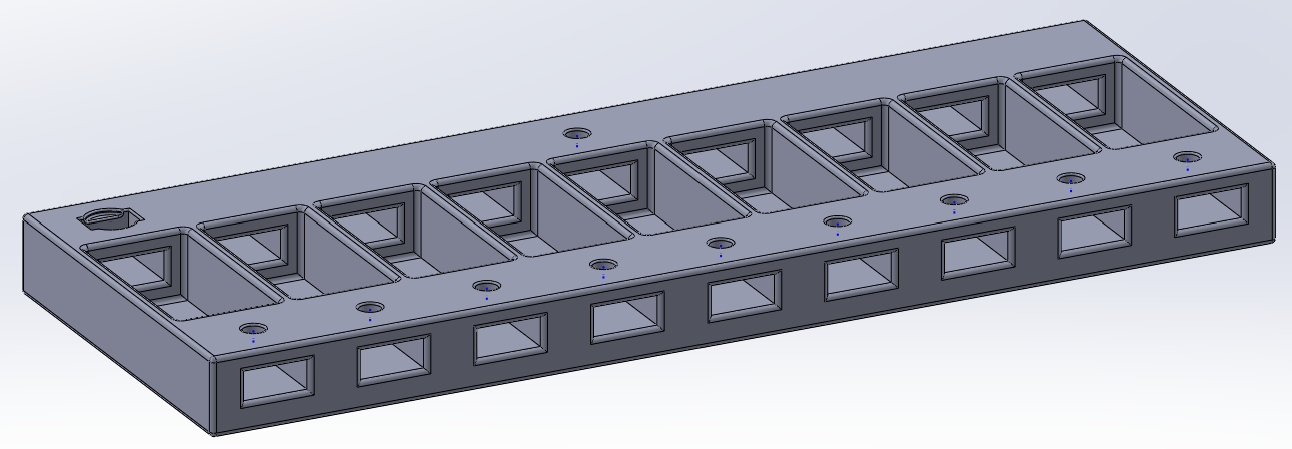
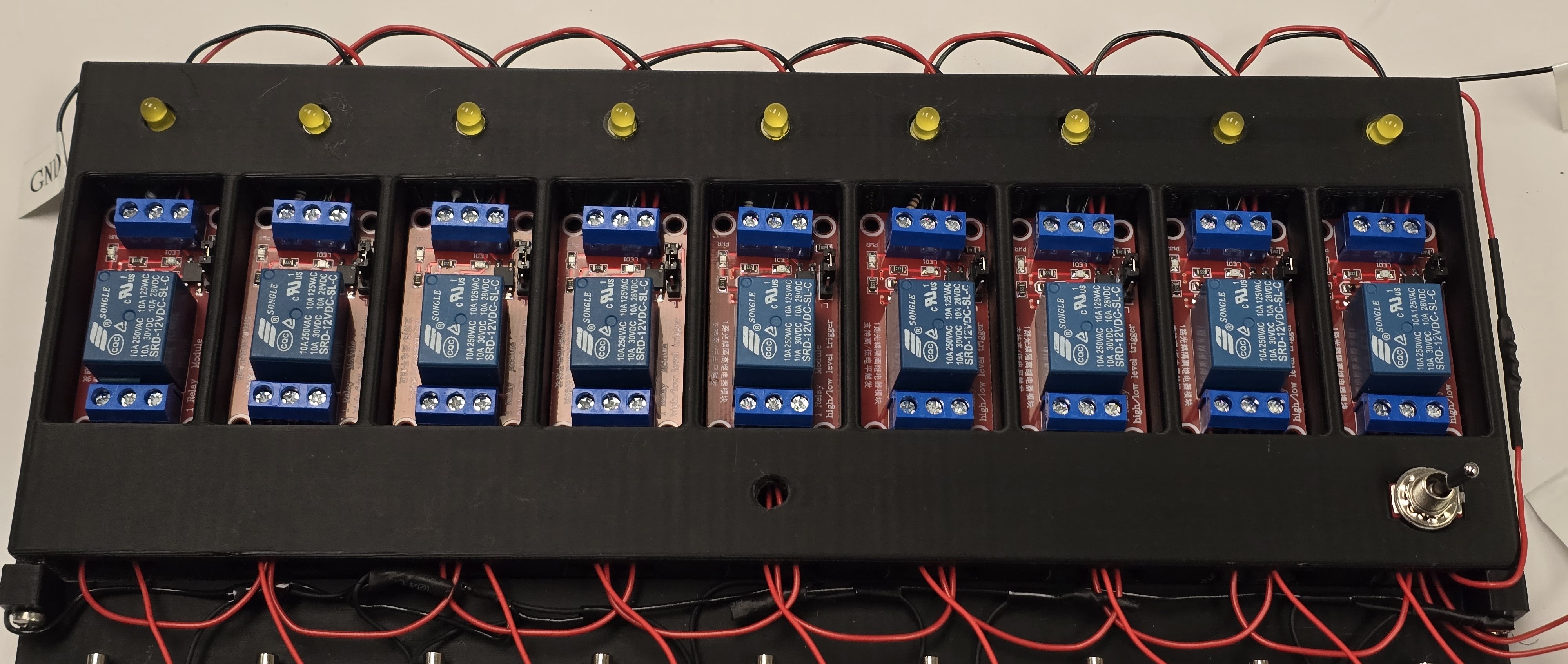
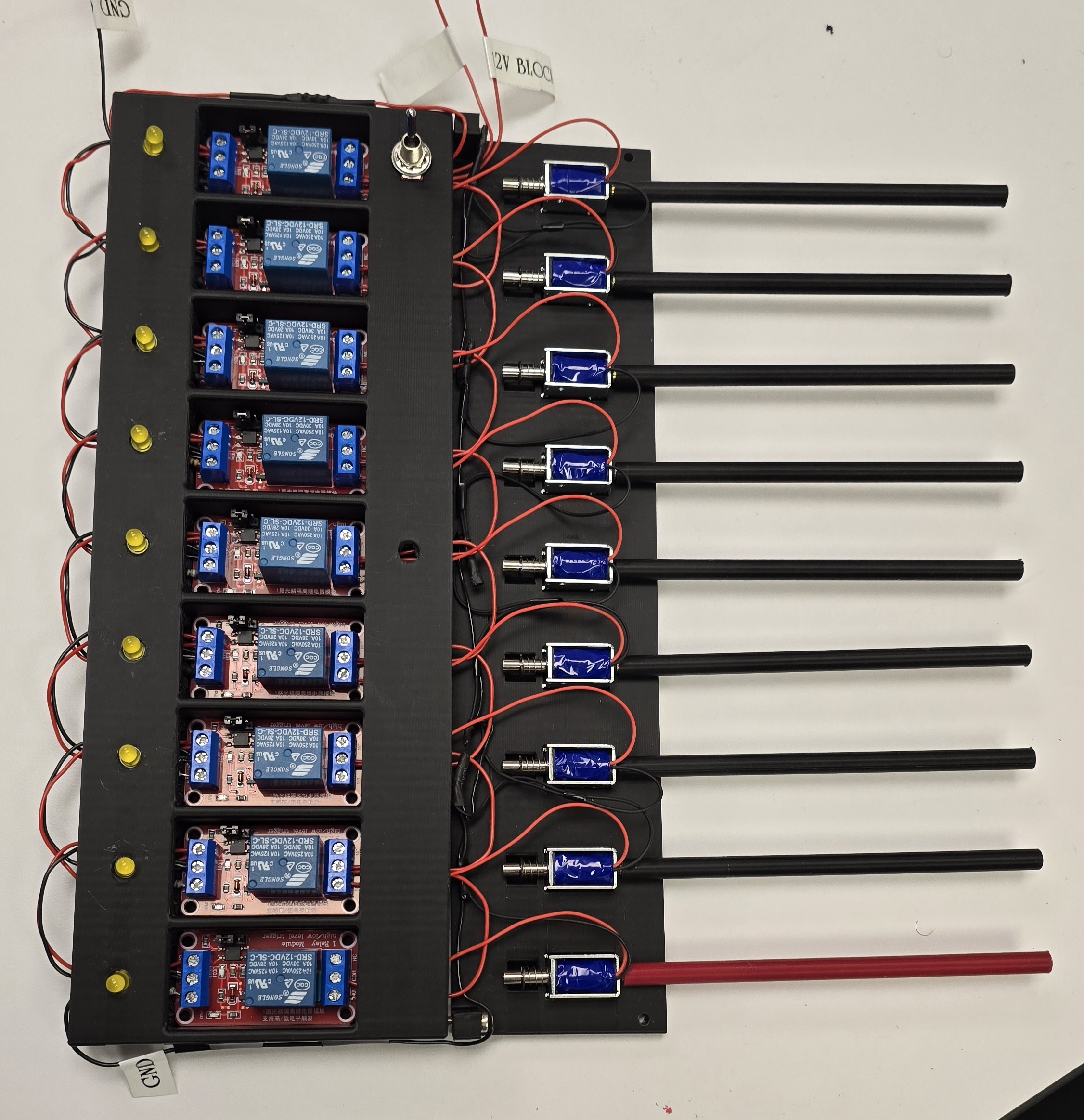
The tiny circular holes shown at the top hold debugging LED that are used to vizualize if the respective signal line is activated. That is, if the FPGA sends a logic HIGH, the LED in that opening lights up. The other huge opening in the top left holds a toggle flip switch that turns ON or OFF the whole block. The wires are daisy chained to reduce the wiring mess. This is possible because all relays are powered by the same voltage, \(12V\), and require the same ground reference. The debugging LED are the hardest to setup. We soldered \(100\Omega\) resistors to the anode legs and bent them to fit into the square openings seen in the block. The other leg of the resistor slots in the signal input terminal of the relay while the LED cathode leg is locked inside the the relay ground terminal. The fully assembled relay block is shown in Figure 2 below:
Soleonid Holder
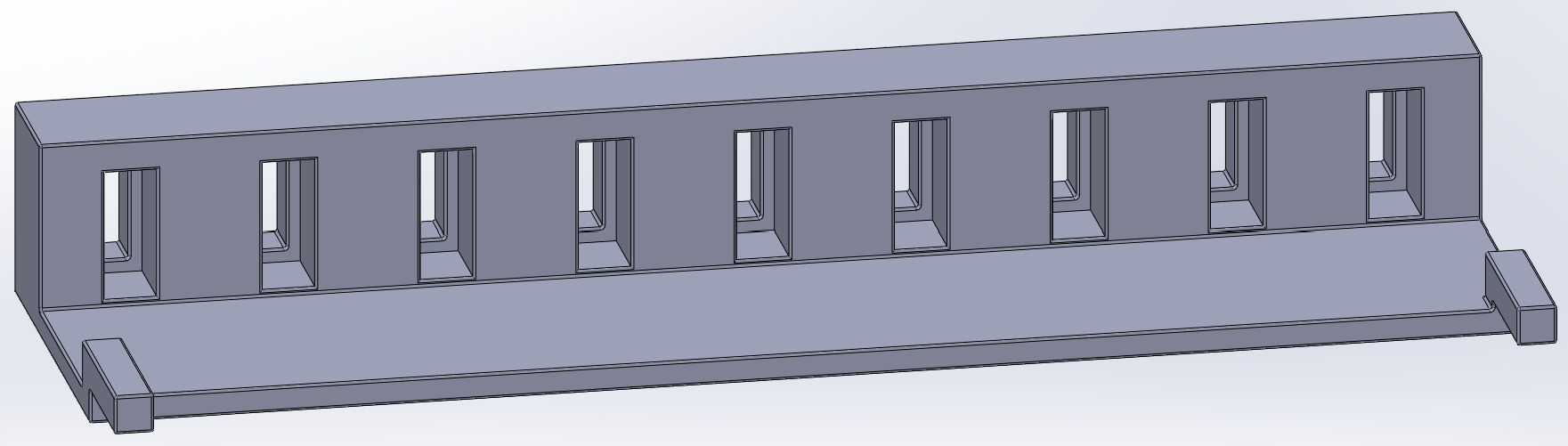
The solenoid block has a square opening to hold the solenoid module. Behind the square holes, there is circular holes that are used create a good clearance for the solenoid spring heads and for them to slide without scraping or locking. The relay block is shown in Figure 3 below:
The extendedstands from the corners are drilled through to house screws that connect and lock the solenoid block to the relay block. The grounds of the individual solenoids are daisy chained as well and conected to the reference ground of the relays while the power ternimals connect to the Normally Closed (NC) exit terminals of the relay. The fully assembled solenoid block is shown in Figure 4 below:
Shaft Guide and Shafts
The shaft guides block was the most straightforward piece with rings that have a good enough opening to accomodate \(0.25in\) thick, \(5in\) long shafts. It also has the seame extensions that help lock it to the solenoid block with screws too. The fully assembly is shown in Figure 5 below:
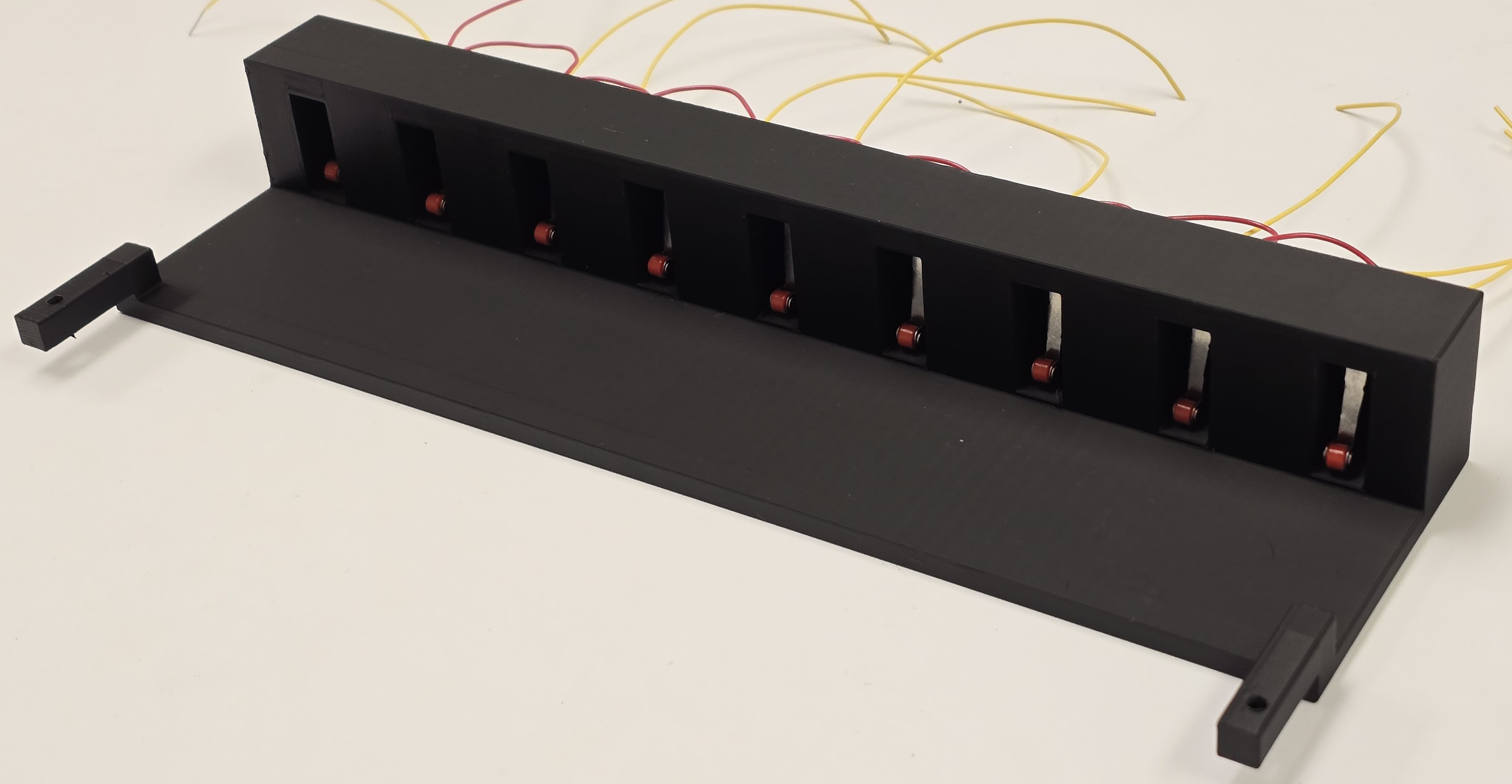
Limit Switch Holder
The limit switch holder was another crucial part. The kick from the solenoids once energized is huge so the block had to be able to stay stable as well as lock the switches so they press insted of being moved back by the solenoids. The switch holder is shown in Figure 6 below:
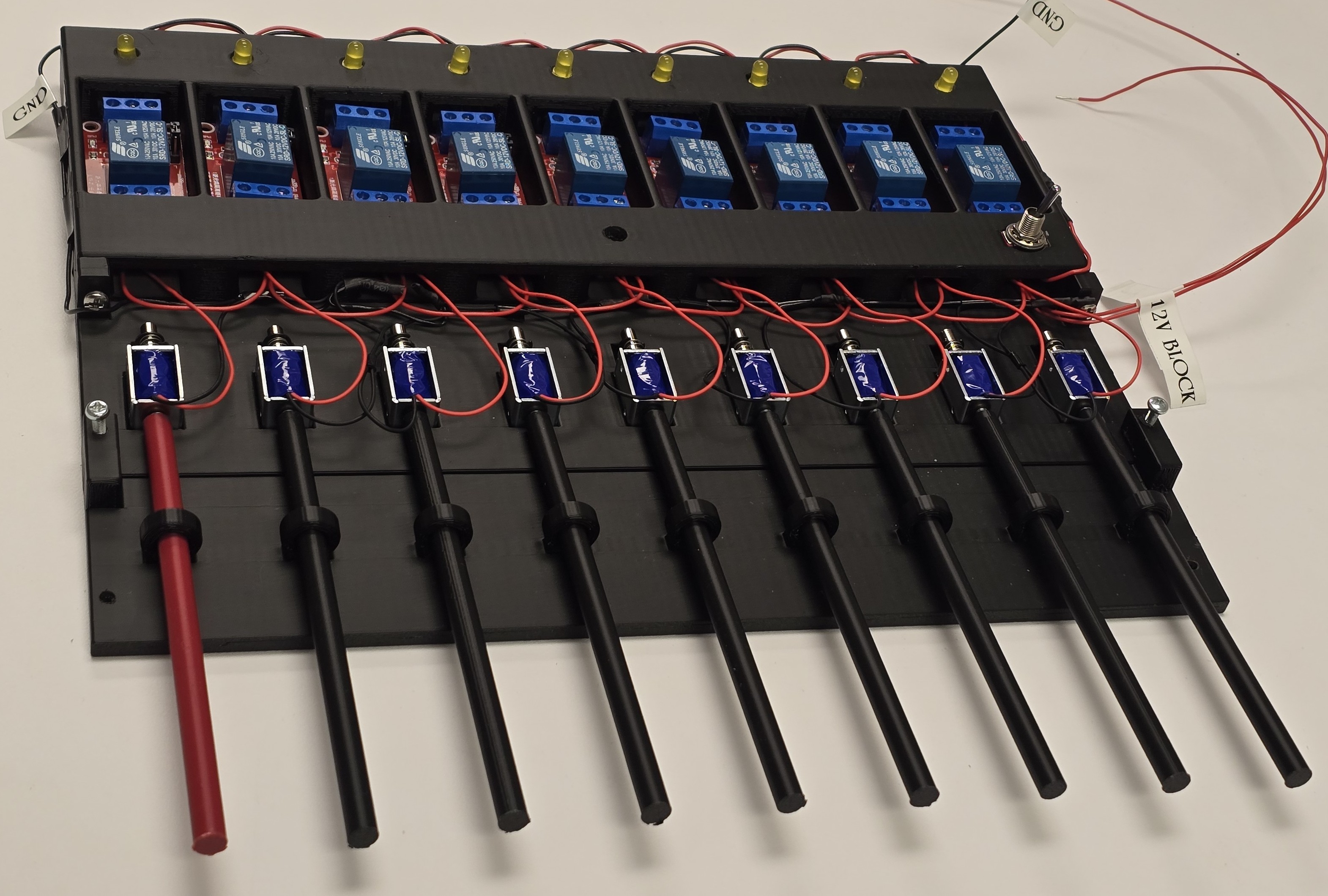
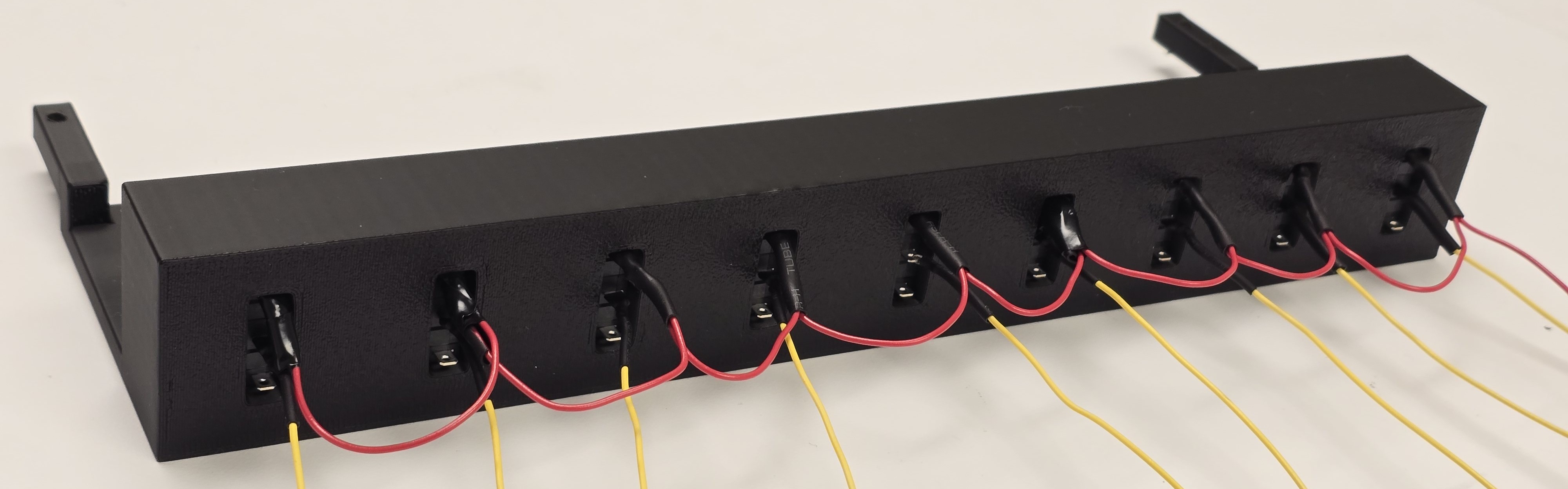
The limit switches also feature daisy chained ground wires extending out of the back of the block as well as signal lines that go to the MCU. The switches are tightly fit and can be moved back or forward to create the necessary distance ensuring better actuation. The fully assembly is shown in Figure 7 and Figure 8 below:
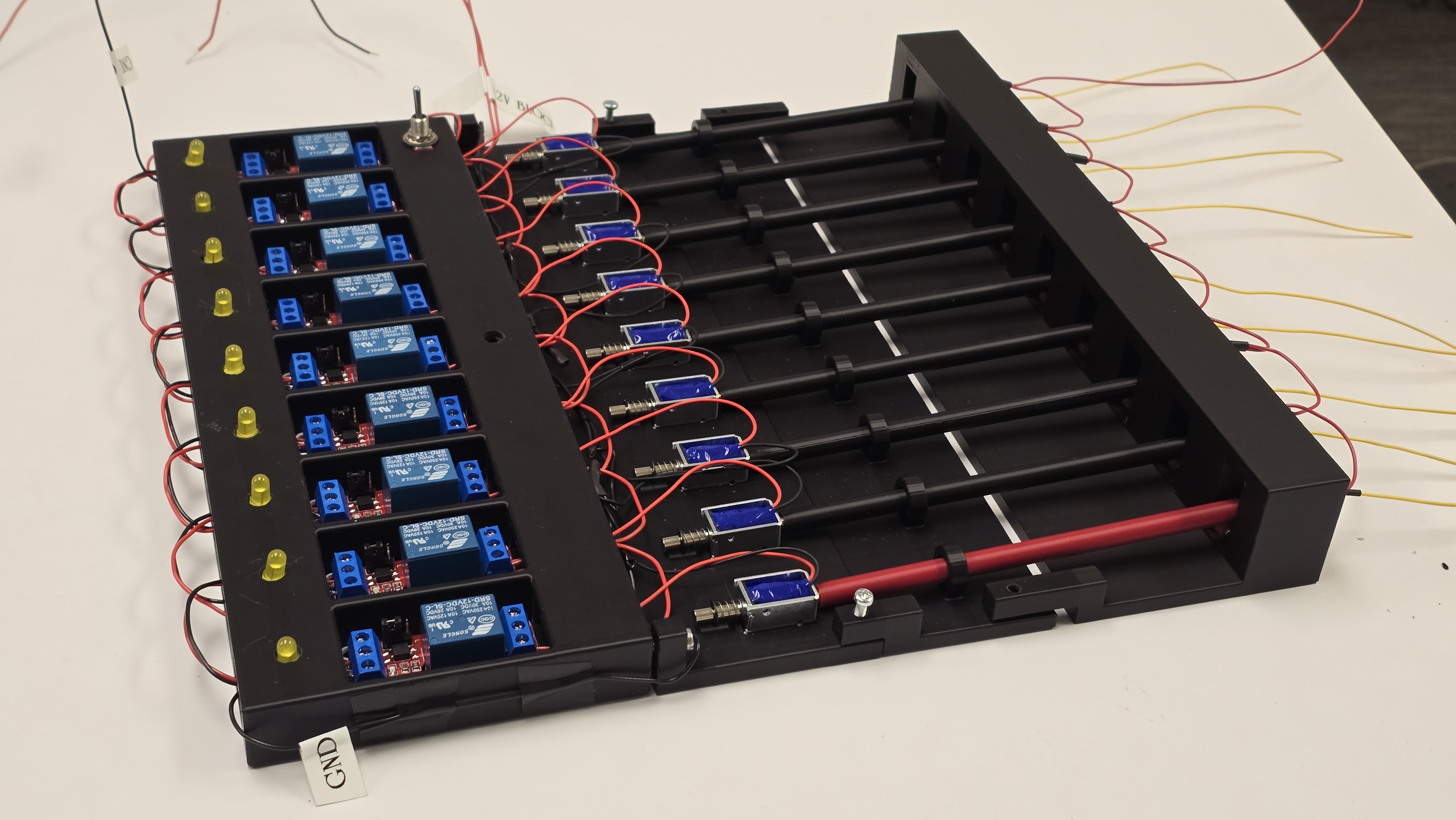
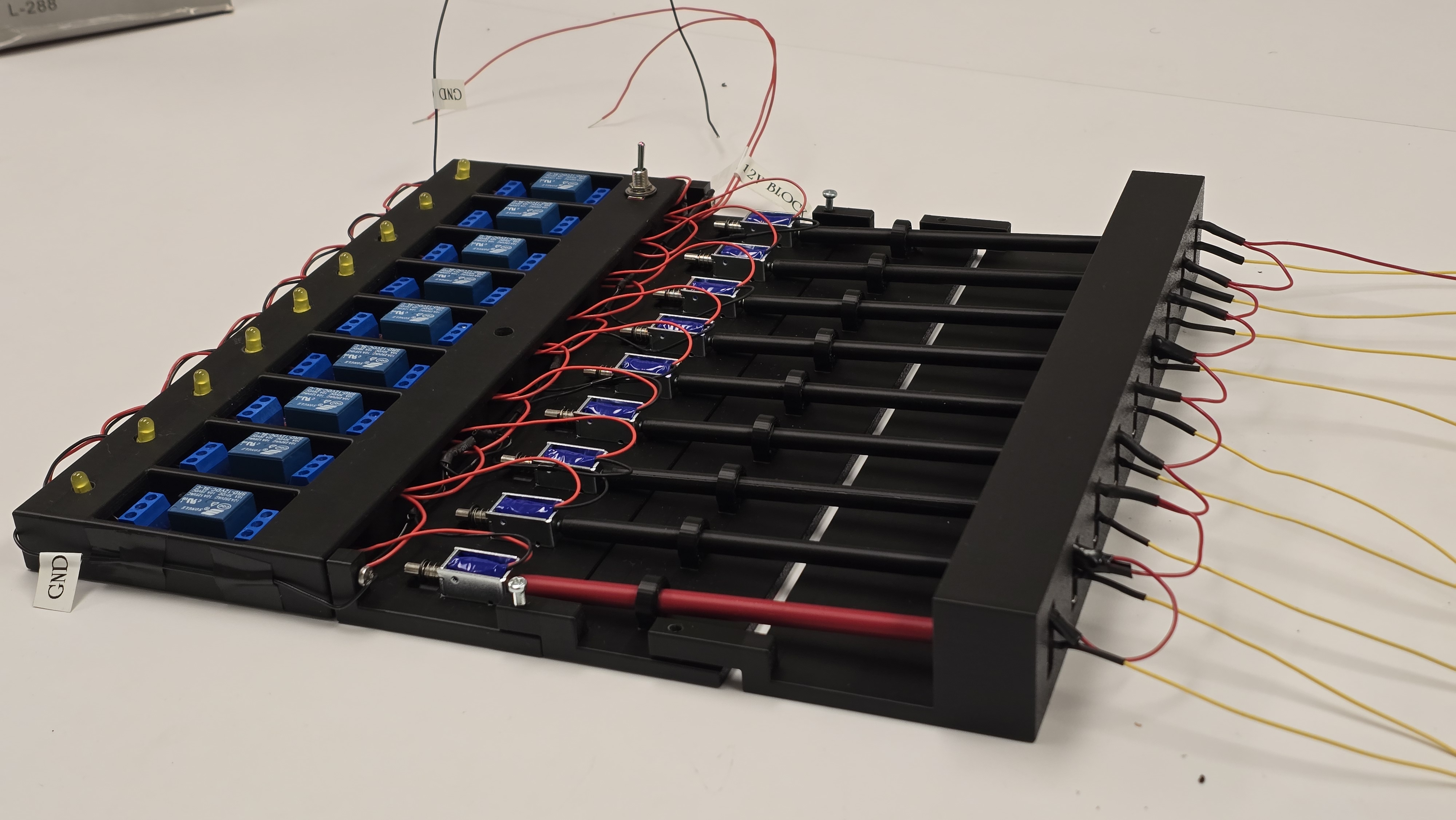
After making all the blocks and fitting the necessary components in each section, the blocks are linked by drilling \(\frac{1}{8}\text{in}\) holes in the shown areas to fit the connecting screws. Connecting all individual components yields the following setup: