Hardware-Accelerated AES Decryption
Introduction
AES decryption is conceptually the mathematical inverse of AES encryption and therefore applies the opposite operations in reversed order. This is only correct to some extent, depending on the specific algorithm used. The implementation in this project uses the Equivalent Inverse Cipher algorithm to recover the plaintext. Similar to encryption, the MCU and FPGA are used where the MCU provides the key and ciphertext while the FPGA performs decryption and sends the plaintext to the MCU via SPI protocol.
Decryption Overview
Just like encryption performs SubBytes(), ShiftRows(), MixColumns(), and AddRoundKey() in that order, decryption uses InvShiftRows(), InvSubBytes(), InvMixColumns(), and AddRoundKey() to retrieve the original plaintext. However, decryption requires AddRoundKey() to occur at the beginning of each round rather than at the end, which breaks symmetry with the encryption pipeline and complicates reuse of hardware. To avoid this, we used Equivalent Inverse Cipher (EIC) which rearranges the the inverse transformations so that the round structure follows the same order and pipeline as encryption which is feasible for hardware resuse and less complicated implementation. Now, all decryption rounds except the final one to follow the same 4-cycle micro-pipeline. However, for this to work, decryption requires additional processing of the key schedule: all keys for round 1 through 9 must be generated early and then premixed using InvMixColumns() before being used in the datapath while keeping round 0 and 10 constant. This means that all the round keys have to be pre-generated before decryption starts. Despite all of this, EIC is still relatively faster and efficient than the traditional Inverse Cipher.
FPGA Setup and Decryption Pipeline
Decryption on the FPGA is divided into two major phases: Key Expansion and Decryption outlined below.
Key Schedule and Premixing
The key schedule uses the same algorithm as encryption, which is advantageous because the AES specification requires that key expansion must use the forward S-box even when decrypting. In this case, the module getNextKeyEIC() behaves like getNextKey() from encryption but uses the combinational S-box, sbox() because we wanted the nextkey to be valid and stored within the same clock cycle. Each generated key was then stored as a raw key in the array roundKeys[]. The freshly generated 128-bit key is passed into inv_mixcolumns(), producing the premixed result which is then stored in the array premixedKeys[] for rounds 1 through 9. This process is gated by specific signals: while ka_busy is active, all key generation and premixing operations proceed, and only after ka_done is asserted does the actual decryption begin.
Decryption Execution
When the load is asserted by the MCU, the system loads the 128-bit input key into currKey and roundKeys[0], while the ciphertext is captured into bfrAdd. The system now begins the key expansion. After ka_done is asserted, decryption begins with roundCount initialized to 10. The first operation applies AddRoundKey() using the raw round 10 key. Once this initial step is complete, the pipeline executes rounds 9 through 1 using the EIC transformations. In cycle 0, the appropriate premixed round key (premixedKeys[roundCount]) is loaded into word, and the current state is pushed into bfrSub. In cycle 1, the inverse SubBytes output, afterSub, becomes valid, and ShiftRows is applied, producing afterShift. In cycle 2, the inverse MixColumns output, afterMix is XORed with the round key through addRoundKey, and the result is fed into bfrAdd. In cycle 3, the newly computed afterAdd value is committed to state, completing the round and preparing the system for the next decrement of roundCount. This pipelined sequence continues identically until round 1 finishes.
The final round (round 0) omits the inverse MixColumns step. Instead, the raw key for round 0 is loaded into word, and after inverse SubBytes and inverse ShiftRows, the output of afterShift is XORed directly with round 0 key to produce the final plaintext. When this result is written to the plaintext register, the module asserts done_decrypt, signaling completion to the MCU.
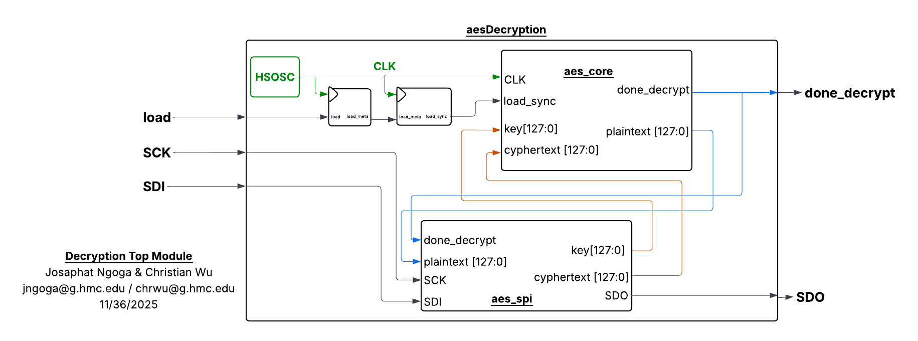
Similar to encrtyption, the pipeline above is wrapped under aes_core() which is called by the aes() top module that also calls aes_spi() meant to execute SPI communication between both the MCU and the FPGA. load is also synchronized to the FPGA clock to eliminate any potential synchronization issues. The connection and signals between these modules is shown in Figure 1.
Design Implementation
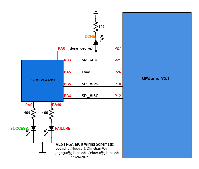
The modules to enforce the AES decryption and those that control the respective decryption transformation algorithms were written in SystemVerilog to run on the FPGA. To ensure proper communication and signal control between the MCU and FPGA, all signals followed the hierachy in the block diagram below:
To ensure proper functionality and communication, the full setup is installed on the development board. The board used already had DIP switches that connect specific MCU pins to specific FPGA pins which reduces the need for crossing wires. Other necessary signals like the debugging LEDs are setup on a side breadboard. The complete setup is shown in the following schematic: