Documentation
Electrical Schematics
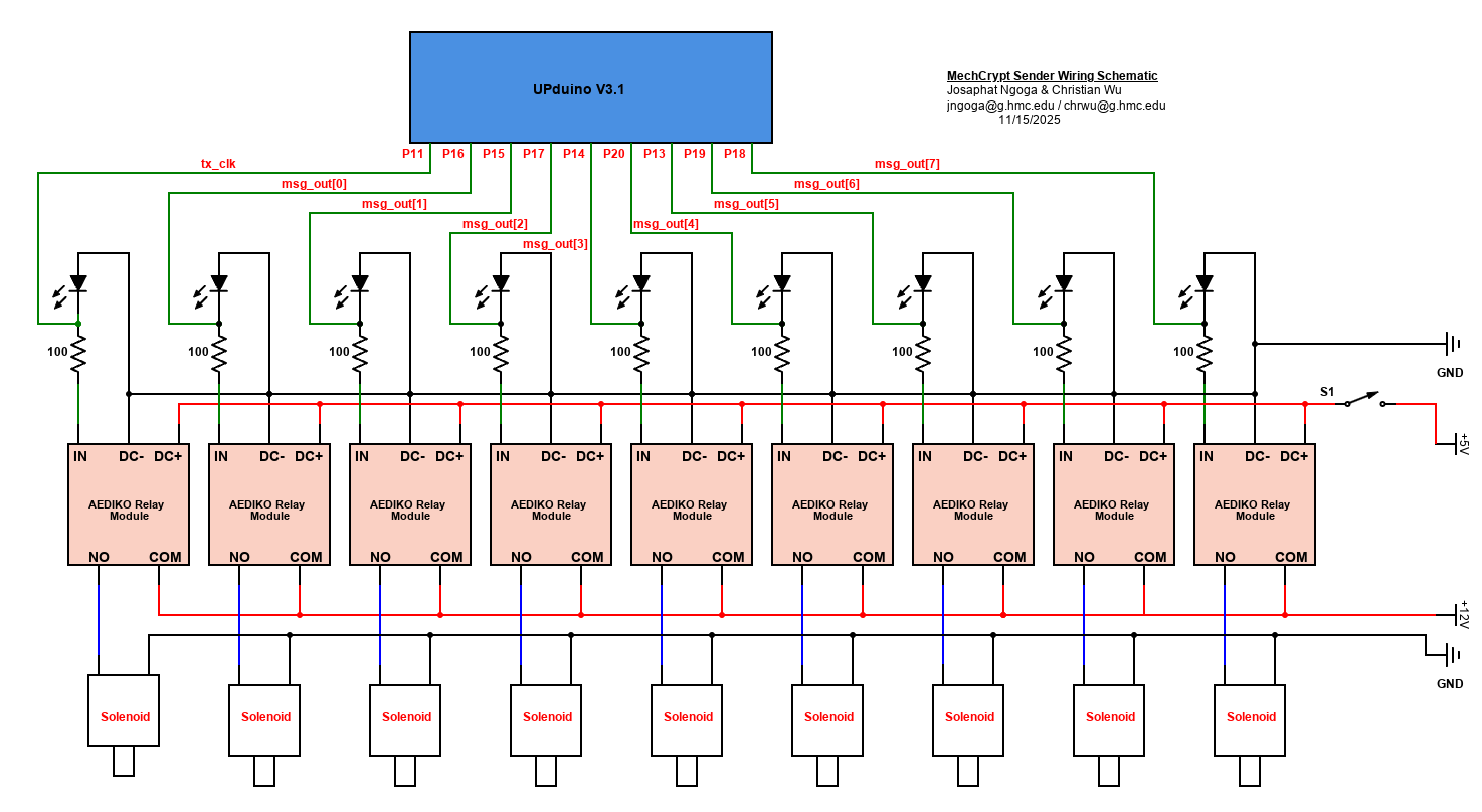
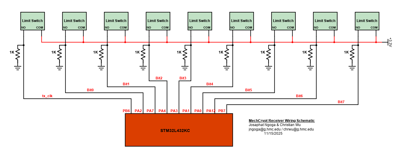
Below are pictures of the electrical schematics for our mechanical actuation system
The assembly of the LCD required a level shifter to boost voltages into the required range as shown below:

Bill of Materials
| Part Name | Part Number | Quantity | Vendor | Price | Link |
|---|---|---|---|---|---|
| 12V Relay Module | SRD-12VDC-SL-C | 10 | AEDIKO | 13.20 | Link |
| 12V Solenoid | Z24G50031OJX | 9 | TEHAUX | 28.26 | Link |
| Roller Lever Arm Micro Limit Switch | KW12-3 | 10 | HiLetgo | 6.60 | Link |
| LCD Display with I2C Adapter | LCD2004 | 10 | SunFounder | 14.26 | Link |
| FPGA | Upduino v3.1 | 2 | Upduino | Stockroom | N/A |
| MCU | STM32L432KC | 2 | STM | Stockroom | N/A |
| 3D Printed Rods | N/A | 9 | N/A | Makerspace | N/A |
| ESP8266 | ESP-WROOM-02 | 2 | Edwin Robotics | Stockroom | N/A |
| 3D Printer & PLA | N/A | N/A | N/A | Makerspace | N/A |
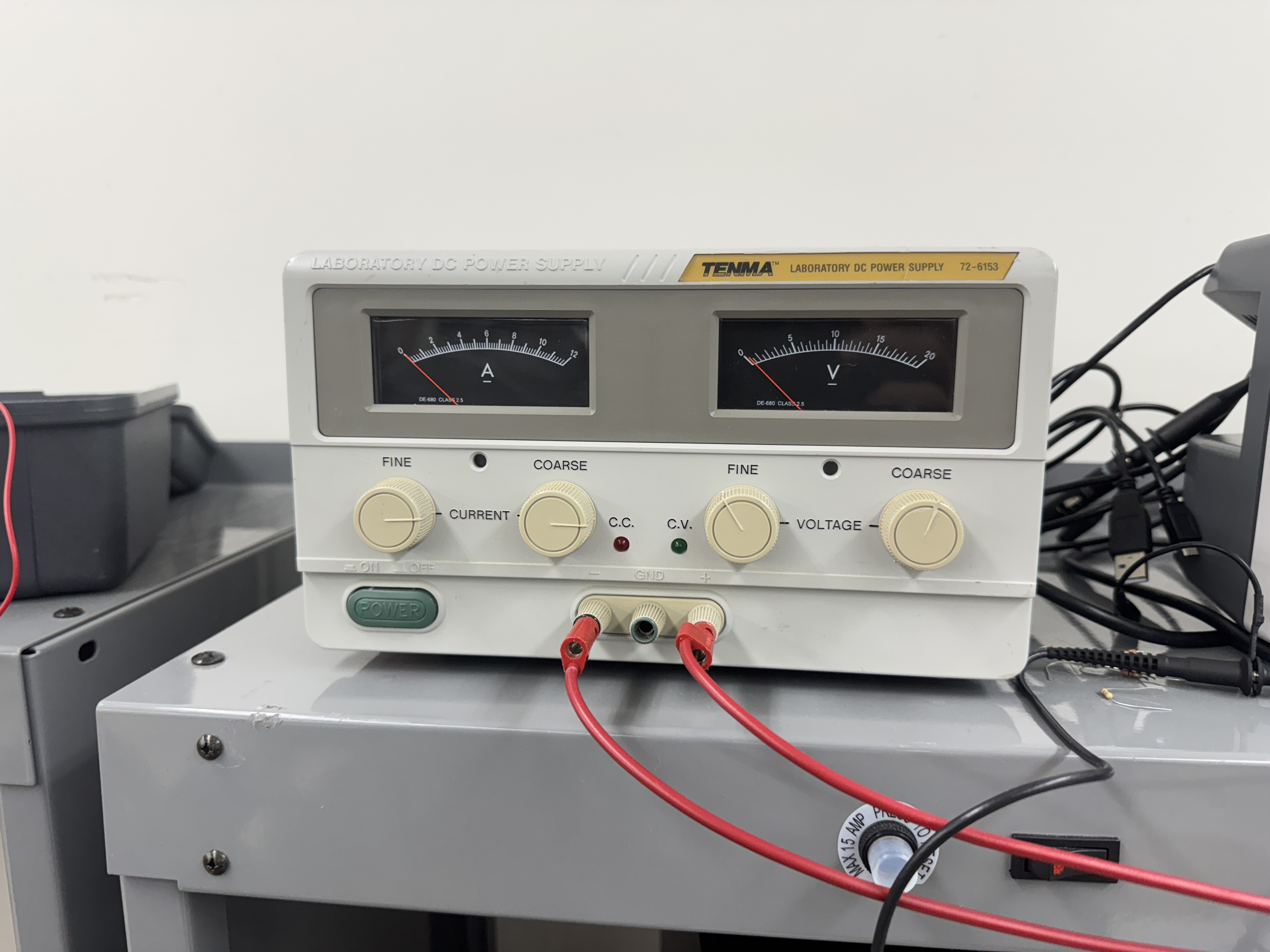
| 20 V 12 A Power Supply | 72-6153 | 1 | TENMA | Stockroom | N/A |
| 20 V 0.5 A Power Supply | E3630A | 1 | HP | Digital Lab | N/A |
| Total | $62.32 |
While we were working on our project, we did not realize how much current our 9 solenoids drew, especially when all of them were on. It was drawing around 0.85 A for each solenoid. The power supply at the digital lab only supplies a maximum of 0.5 A on the 20 V setting, which means we would always overload the power supply. Thus, we were able to use a big power supply that was in the stockroom, which supported up to 12 Amps. Below is a picture of the power supply:
Acknowledgements
We would like to thank Prof Spencer for his detailed feedback and support throughout the project, guiding us in the right direction to solve problems. We would also like to thank Xavier for helping us with the ideation process for the project and ironing out any issues and confusions that we had. We would also like to thank Jacob for his kindness and support, and willingness to help us find all the parts we needed for this project.